

How to Choose the Right Threaded Linear Shaft?
Choosing a Threaded Linear Shaft is not just a matter of matching its diameter to a drawing. The right choice depends on how the mechanism moves, what it carries, and where it operates. A shaft in a compact positioning stage may face different demands from one supporting a sliding guard or adjustment table. Small details matter.
Start with the application’s measurable requirements: travel distance, load, speed, duty cycle, and acceptable positioning error. Then compare shaft diameter, thread pitch, material, surface finish, and end support. A finer pitch can improve adjustment resolution, but it may reduce travel speed. Greater diameter can increase stiffness, though it also adds weight and may require more space. There is no universally best specification.
Check the manufacturer’s drawings and ratings rather than relying on product names alone. Terms such as threaded shaft, lead screw, and linear shaft can be used differently across suppliers. Confirm thread form, dimensional tolerances, compatible nuts, and mounting details before ordering. Also consider dust, moisture, temperature, and lubrication needs. These conditions can change wear and maintenance requirements.
Keep the load path in view. Misalignment or unsupported shaft length can cause deflection, binding, or uneven wear, even when the selected shaft appears strong enough. That sounds obvious, yet it is often missed. Review the full assembly, not just one component. If the application is critical, ask the supplier to verify the selection against your operating data, then test a sample under realistic conditions. A careful choice balances performance, service life, installation effort, and cost—and leaves room to revise assumptions when actual measurements disagree.
Understand Threaded Linear Shafts and Their Main Components
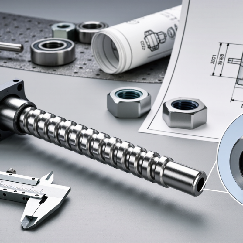
A threaded linear shaft is a rotating or stationary metal rod with a helical thread that guides a matching nut along a straight path. The shaft, nut, and support bearings form the core assembly. A motor and coupling may drive the shaft, while a guide rail helps prevent the nut from twisting under load. Each part has a distinct job.
Thread pitch determines how far the nut travels per revolution. A finer pitch can support smaller movement increments, while a coarser pitch may move the load farther with each turn. Check the shaft’s diameter, usable length, load, speed, and expected duty cycle before choosing.
Material and surface finish matter, too; dust or inadequate lubrication can increase wear. Small details matter. In a practical installation, shaft supports must hold alignment along the full travel, not just at the ends. Misalignment can cause binding, noise, or uneven wear.
It is easy to focus too much on pitch. I would also check how the nut is secured and whether maintenance access is realistic. The right combination depends on the machine and operating conditions.
A selection can look sound on paper, yet prove awkward to service.
Define the Required Load, Travel, Speed, and Accuracy
How to Choose the Right Threaded Linear Shaft?
Define the Required Load, Travel, Speed, and Accuracy
Choosing the right threaded linear shaft starts with defining what it must carry and how it will move. Record the total moving mass, including the carriage and tooling, then estimate axial force during acceleration and operation. Side loads matter too; a shaft sized around axial force alone may bend or wear unevenly. Keep a safety margin, but avoid oversizing without checking inertia and drive requirements.
Next, specify travel, speed, and duty cycle in real terms. A 300 mm stroke at 20 mm/s differs from the same stroke repeated every few seconds. Check the thread lead: a greater lead can increase travel per revolution, but may require more torque and reduce positioning resolution. Measure it twice. Accuracy should include repeatability, backlash, and the tolerance of the surrounding structure, not just the shaft specification. A rigid mounting plate can still shift under load.
Use the actual mounting distance and support arrangement when checking deflection and critical speed. Include dust, temperature, and lubrication in the operating conditions. Real conditions differ. Start with calculations, then test under a representative load and speed. Record noise, temperature, and positional error. Revisit your assumptions if readings drift; the first estimate is useful, not sacred.
Choose the Shaft Material, Diameter, and Thread Type
How to Choose the Right Threaded Linear Shaft?
Material and Working Conditions
Start with the working environment and load. Carbon steel suits many demanding applications, but moisture can cause corrosion. Stainless steel resists rust, though its strength and wear behavior depend on the grade. Aluminum reduces moving mass, but it may wear faster under concentrated loads. Check the shaft’s support spacing, expected load, speed, and exposure before choosing. A material that looks ideal on paper may disappoint in a damp workshop.
Diameter, Thread Profile, and Pitch
Diameter affects stiffness as well as fit. A thicker shaft can reduce bending, especially across longer unsupported spans, but it also adds weight and may require larger bearings. Match the diameter to the supports and connected parts, then check manufacturer load data. For the thread, choose a trapezoidal or Acme-style profile when the shaft must transmit motion and force. Standard metric threads are often better for fastening or adjustment. Pitch and lead influence travel per turn; finer threads offer smaller movement, while coarser leads can move a carriage faster. Backlash matters too. It is easy to overlook until positioning becomes inconsistent.
Tips
Measure the full assembly, not just the shaft. Confirm thread direction and pitch with a gauge. Leave room for misalignment; real frames are rarely perfect. Recheck the choice if dust, side load, or frequent reversals are part of the job.
Check Compatibility with Bearings, Nuts, and Drive Components
A threaded linear shaft must match its bearing seats, not just its nominal diameter. Measure the shaft journal and bearing bore, then check fit class, shoulder position, and runout against the assembly drawing. A shaft that feels smooth by hand can still bind under load. Small mismatch, big trouble. ISO 286 defines standardized tolerance zones and fits, giving engineers a common basis for specifying these dimensions.
Match the nut to the thread form, pitch, lead, and hand; identical diameters alone do not guarantee compatibility. Check usable travel and backlash, too, especially where the nut approaches a support block. For bearings, ISO 281 gives the basic ball-bearing rating-life relation: L10 = (C/P)^3 million revolutions, where C is dynamic load rating and P is equivalent dynamic load. It helps estimate bearing life, but does not account for poor alignment or contamination. Check the drive end as well: coupling bore, keyway or flat, shoulder length, and allowable torque must suit the motor or gearbox. Measure the existing parts where possible. Drawings can be old, and real assemblies are not always perfect.
| Component or Check | What to Verify | Compatibility Requirement | Example or Practical Guidance |
|---|---|---|---|
| Thread form and nominal size | Confirm the thread profile, nominal diameter, and pitch or lead. | The shaft and nut must use the same thread form and matching dimensions. A trapezoidal thread is not interchangeable with an Acme or metric V-thread merely because the nominal diameter is similar. | Metric trapezoidal examples include Tr8×1.5 and Tr12×3. Check the drawing or product specification for the exact thread designation. |
| Nut hand and lead | Check right-hand or left-hand thread and the distance the nut travels per shaft revolution. | The nut’s hand and lead must match the shaft. For multi-start threads, lead differs from pitch; lead equals pitch multiplied by the number of starts. | A single-start Tr12×3 thread has a 3 mm lead. A multi-start thread with the same pitch can have a greater lead. |
| Bearing fit and shaft journal | Check bearing bore, journal diameter, fit tolerance, and shoulder dimensions. | Bearings typically mount on a smooth, accurately sized journal—not directly on the threaded section. The journal must suit the bearing bore and specified fit. | A bearing with a 10 mm bore requires a compatible 10 mm journal, subject to the bearing and application’s fit requirements. |
| Radial and axial load support | Determine whether the system needs radial support, axial thrust support, or both. | Do not assume a radial support bearing alone can handle the screw’s axial load. Select and arrange supports according to the load direction and bearing ratings. | Use a suitable thrust-capable arrangement where the screw must react significant axial force; check static and dynamic load ratings. |
| Nut mounting and alignment | Check nut housing dimensions, mounting pattern, clearance, and alignment with the shaft. | The nut must be secured without forcing it out of alignment. Misalignment can increase friction, wear, and binding. | Compare the nut’s mounting drawing with the carriage or bracket drawing, including bolt spacing and available clearance. |
| Coupling or pulley interface | Check the shaft-end diameter, keyway or clamp style, and available engagement length. | The drive component must fit the machined shaft end and transmit the required torque. Do not select it using the thread’s nominal diameter alone. | Match a coupling bore to the actual motor and screw-end diameters; check the coupling’s torque and misalignment ratings. |
| Motor speed and travel | Match motor speed and screw lead to the required linear travel rate. | Approximate travel speed equals rotational speed multiplied by lead, using consistent units. Higher lead increases travel per revolution but can reduce mechanical advantage. | At 600 rpm, a 4 mm lead gives a theoretical travel speed of 2,400 mm/min before accounting for operating limits. |
| Stroke and end machining | Check usable thread length, support locations, shoulders, and drive-end features. | The threaded working length must cover the required stroke and nut length, while the machined ends must accommodate bearings and drive parts. | Allow for end supports, nut length, and any required overtravel when specifying overall shaft length. |
| Speed, buckling, and critical speed | Evaluate unsupported length, end-support arrangement, rotational speed, and compressive load. | A long or slender screw may be limited by buckling or rotational vibration before reaching the motor’s maximum speed. | Use the screw supplier’s critical-speed and buckling calculations for the actual diameter, length, and support conditions. |
| Accuracy and backlash | Specify positioning accuracy, repeatability, and allowable axial play. | Thread lead accuracy and nut clearance affect motion performance. A standard nut may have more backlash than a preloaded design. | For positioning tasks, compare the stated lead accuracy and backlash with the system’s required tolerance. |
| Lubrication and environment | Check material, lubricant, temperature, contamination, and maintenance needs. | Lubrication and material pairing must suit the application. Dust, moisture, or inadequate lubrication can accelerate wear. | Follow the component manufacturer’s lubrication guidance and consider shielding the thread in contaminated environments. |
Selection note: Threaded shaft dimensions and performance vary by standard and manufacturer. Confirm the shaft, nut, bearing, and drive-component drawings before ordering or assembly.
Compare Operating Conditions, Maintenance Needs, and Total Cost
How to Choose the Right Threaded Linear Shaft?
Compare Operating Conditions, Maintenance Needs, and Total Cost
A threaded linear shaft should match the actual load, travel distance, speed, and surroundings. A dusty workshop, for example, can contaminate exposed threads and increase wear. Check whether the shaft will face side loads, frequent starts, or long idle periods. These details affect material, thread pitch, support, and lubrication choices. A catalog rating alone may miss the real operating pattern.
Maintenance changes the cost calculation. Include lubricant, inspection time, alignment, replacement parts, and downtime—not just the purchase price.
A simple comparison over expected service hours can expose a low-price option that needs frequent attention. Estimates can still be wrong; real dust and duty cycles are hard to predict.